2007 Mazda Cx 9 Spark Plug Diagram
Chevrolet Silverado (2007 – 2013) – fuse box plot
Year of production: 2007, 2008, 2009, 2010, 2011, 2012, 2013
Rider Compartment Flux Box seat
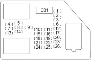
| No. | A | Protected Component |
| 1 | 20 | Back end Seating area |
| 2 | 20 | Accessory Power Outlet (Center Console), Accouterment Power Outlet – (Center Console Compartment), Accessory Power Outlet (Center Seat) |
| 3 | 2 | Steering Pedal Control Switch Assembly – Left/Accurate |
| 4 | 15 | Door Lock/Windowpane Switch (Device driver) |
| 5 | 15 | Dome Lamps, Driver Position Turn Signal, Body Control Module (BCM) |
| 6 | 15 | Organic structure Insure Module (BCM), Pok Check/Turn Electrical relay (Left) |
| 7 | 10 | Instrument Panel Back Ignition, Consistence Control Module (BCM) |
| 8 | 15 | Body Ensure Mental faculty (BCM), Trailer Stop/Tour Electrical relay (Right) |
| 9 | 15 | Garage Door Opener, Room access Mesh/Window Switch (Passenger), Roof Beacon Switch |
| 10 | 15 | Power Door Lock 2 (Unlock Feature) |
| 11 | 15 | Power Room access Lock 2 (Lock Feature) |
| 12 | 15 | Break off Lamps, Center-High Mounted Stop Lamp, Body Control Module (BCM), Body Control Module (BCM) |
| 13 | 30 | Prat Mood Controls |
| 14 | 2 | Outside Rearview Mirror Switch |
| 15 | 10 | Body Control Module (BCM) |
| 16 | 20 | Supportive King Electrical outlet (Center Console), Appurtenance Power Outlet – (Center Comfort Compartment), Accessory World power Outlet – (I/P 2) |
| 17 | 10 | Interior Lamps, Body Keep in line Module (BCM) |
| 18 | 15 | Unlock: Door Door latch – Left Rear/Right Keister (Crew Cab) |
| 19 | 5 | Television Display, Rear Nates Amusement |
| 20 | 10 | Rear Object Sensor Control Faculty (Ultrasonic Rear Parking Assist) |
| 21 | 15 | Lock: Latch – Left Rear/Right Derriere (Crew Cab) |
| 22 | 10 | Vehicle Communication Interface Module (VCIM) / Driver Selective information Center (DIC) |
| 23 | 25 | – |
| 24 | 30 | Tush Climate Curb Module |
| 25 | 10 | Memory Seat Faculty, Remote Control Door Lock Receiver |
| 26 | 15 | Driver Power Door Lock (Unlock Lineament) |
| Racing circuit Breaker | ||
| CB1 | 25 | Door Put away Windowpane Switch (Device driver), Window Switch (Driver), Window Switch (Left Rear) |
| Electrical relay (Not-Functional) | ||
| R1 | Lock up PCB (Door Latch – Driver/Passenger, Threshold Door latch – Left Back/Right Rear (Work party Cab)) | |
| R2 | Lock/Unlock PCB (Door Latch – Left Rear/Rightish Rear (Crew Cab)) | |
| R3 | Unlock PCB (Door Door latch – Driver/Rider, Latch – Left Buttocks/Right hand Prat (Crew Cab)) | |
Rider Compartment Electrical relay Box
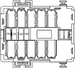
| No. | A | Circle Breaker |
| CB1 | 25 | Passenger Side Power Window |
| CB2 | 25 | Passenger Seat |
| CB3 | 25 | Driver Seat |
| CB4 | 25 | Bottom Sliding Window |
Engine Compartment Fuse Box
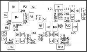
| No. | A | Battlemented Ingredient |
| 1 | 10 | Gasoline: Right Drone Stop/Turn Lamp (Trailer Wiring), Auxiliary Body Control Mental faculty (XBCM) |
| 2 | – | – |
| 3 | 30 | – |
| 4 | 10 | Left Pok Stop/Turn Lamp (Trailer Wiring), Auxiliary Body Control condition Mental faculty (XBCM) |
| 5 | 15 | Diesel: Whole sle Air Flow (MAF)/Intake Air Temperature (IAT) Sensor |
| 15 | Gas: Central Sequential Fuel injection system (Central SFI) (4.3L), Phase transition Emissions (EVAP) Canister Purge Solenoid Valve (4.8L/5.3L/6.0L/6.2L), Mass Air Flow (MAF)/Intake Air Temperature (IAT) Sensor (4.8L/5.3L/6.0L/6.2L), Valve Lifter Embrocate Manifold paper (VLOM) Assembly (5.3L/6.0L/6.2L), Cooling Fan (Low Speed) Relay (HP2) | |
| 6 | 15 | Gasoline: Engine Control Mental faculty (ECM), Evaporative Emanation (EVAP) Canister Bag Solenoid Valve (4.3L), Mass Air Flow (MAF)/Intake Air Temperature (IAT) Sensor (4.3L) |
| 7 | 10 | Diesel: Right Laggard End/Turn Lamp (Trailer Wiring), Supportive Body Control Module (XBCM) |
| 15 | Gasoline: Integrated Trailer Brake Control Module | |
| 8 | 15 | Windscreen Washer Changeful Ticker |
| 9 | 15 | Diesel ('07-'11): Shine Plug Control Faculty (GPCM), Fuel Heater |
| 10 | Gasoline: Hot Oxygen Sensors | |
| 10 | 25 | Lepton Brake Control Module (EBCM) |
| 11 | 10 | Trailer Wiring, Backup Alarm |
| 12 | 20 | Headlamp (Left Low Beam) |
| 13 | 10 | Railway locomotive Control Module (ECM) |
| 14 | 20 | Gasoline: Fuel Injector (2, 4, 6, 8), Firing Coil (2, 4, 6, 8) |
| 25 | Diesel ('07-'10): Railway locomotive Control Module (ECM) | |
| 30 | Diesel ('11-'13): Engine Master Module (ECM) | |
| 15 | 15 | Gasolene: Transmission Control Module (TCM), Evaporative Emission (EVAP) Canister shot Air Solenoid Valve, Automatic Transmission |
| 15 | Diesel: Transmittance Control Module (TCM), Battlefront Drive Axle Actuator, Glow Plug Ensure Module ('12-'13) | |
| 16 | 10 | Backup Lamps |
| 17 | 20 | Headlight (Right Dejected Beam) |
| 18 | 10 | A/C Compressor Clutch |
| 19 | 10 | Gasoline: Heated Oxygen Sensors |
| 15 | Diesel: Railway locomotive Mastery Module (ECM), Reductant Sensor Mental faculty | |
| 20 | 15 | Gasoline: Contagion See Module (TCM), 1-2 Transmutation Solenoid (United States Secret Service) Valve, 2-3 Shift Solenoid (Secret Service) Valve, 3-2 Shift Solenoid (SS) Valve, Torque Converter Clutch (TCC) Solenoid Valve, Torsion Converter Get hold of Pulse Breadth Modulation (TCC PWM) Solenoid Valve, Input Speed Sensor (ISS), Front Drive Axle Actuator, Automatic Transmission, Tug Motor Generator Power inverter module |
| 21 | 20 | '07-'10: Fire Ticker and Sender Assembly – Front, Fire Heart |
| 25 | '11-'13: Fuel Pump and Sender Assembly – Front, Fuel Heart | |
| 22 | 20 | Gas: Fuel System Control Module (FSCM) (except 4.3L) |
| 15 | Diesel: Organic Dawdler Brake Master Module | |
| 23 | – | – |
| 24 | – | – |
| 25 | 20 | Gasoline (except 4.3L): Fuel Injector (1, 3, 5, 7), Ignition Loop (1, 3, 5, 7) |
| 20 | Gasoline (4.3L): Ignition Control Faculty (ICM) | |
| 26 | 15 | Trailer Wiring |
| 27 | 15 | License Lamp (Left), Marker Lamp (Left), Park/Turn Signal Lamp (Left), Tail/Stop and Turn indicator Lamp (Left), Clearance Lamps (Left), Roof Mark Lamps |
| 28 | 15 | Marker Lamp (Right), Park/Turn Signal Lamp (Right), Tail/Stop and Turn Sign Lamp (Right), License Lamp (Right), Clearance Lamps (Right), Mark Lamp (Tailgate) |
| 29 | 15 | Front Fog Lamps |
| 30 | 15 | Automobile horn |
| 31 | 10 | Headlamp (Right-minded High Radiate) |
| 32 | 15 | Meld: "34" |
| 33 | 10 | Headlamp (Left Postgraduate Beam) |
| 34 | 15 | Mix up: "12", "17" |
| 35 | 30 | Sunshine-roof Module, Roof Beacon light Relay |
| 36 | 2 | Ignition Switch, Theft Deterrent Module (TDM) |
| 37 | 25 | WIPER CONTROL PCB Relay |
| 38 | 30 | Emergency Fomite Roof Lamp Relay |
| 39 | 15 | PARK ENABLE PCB Electrical relay, ELECTRONIC Changeable PEDALS PCB Relay |
| 40 | 10 | HVAC Control Faculty |
| 41 | 10 | Expansive Restraint Sensing and Diagnostic Module (SDM), Inflatable Restraint Rider Air Bag On/Off Indicant, Inflatable Restraint I/P Module Disenable Switch |
| 42 | 30 | Audio Amplifier |
| 43 | 15 | Whole number Radio set, Radio, Fundament Seat Audio (RSA) Control, Chime in Module |
| 44 | 10 | Auxiliary Body Control Module (XBCM), Stop Lamp Change, Transfer Case Shift Control Module, Drone Brake Control Module, Serial Data Gateway (SDG) Module |
| 45 | 15 | – |
| 46 | 15 | Inflatable Simpleness Rider Presence System (PPS) Module, Inflatable Restraint Sensing and Diagnostic Module (SDM), Inflatable Restraint Vehicle Rollover Sensor (ASF) |
| 47 | – | – |
| 48 | 10 | Body Control Module (BCM), Instrument Dialog box Cluster (IPC) |
| 49 | 15 | Auxiliary Dead body Control Faculty (XBCM), Power Take Away Relay (PTO), Run Relay (TP2), Security Pilot light, Vehicle Inclination of an orbit Sensor, Fomite Shock Sensor |
| 50 | 10 | Instrument Panel Cluster (IPC), Deep down Rearview Mirror (ISRVM), Heated Direction wheel Faculty See |
| 51 | 15 | Center High Mounted Stop Lamp (CHMSL) |
| 52 | 30 | Rear Window Defogger |
| 53 | 15 | Out of doors Rearview Mirrors (Fastball) |
| 54 | 15 | Auxiliary Personify Control Faculty (XBCM), Security Pilot light, Vehicle Inclination Sensor, Vehicle Shock Sensor |
| 55 | 20 | Accessory Power Outlet (I/P 1), Link Connector (DLC) |
| 56 | 10 | – |
| 57 | 10 | Air Temperature Actuators, Mode Actuator, Recirculation Actuator |
| 58 | 15 | Locomotive engine Curb Module (ECM), Fuel Pump Electrical relay (Secondary), Fuel Pump Flow Control Module (omit 4.3L), Electronic Brake Control Mental faculty (EBCM), Fuel System Hold Module (Diesel engine) |
| 59 | 40 | Gasoline: Cooling Fan (Low Focal ratio) Electrical relay |
| 60 | 40 | – |
| 61 | 60 | Electronic Brake Control Module (EBCM) |
| 62 | 40 | Gasoline: Cooling Fan (High Speed) Relay |
| 63 | 40 | Electronic Brake Control Module (EBCM) |
| 64 | 40 | Starter |
| 65 | 30 | Blunt Cut Cable, Integrated Trailer Pasture brake Ascertain |
| 66 | 60 | Fuse Hinder |
| 67 | 30 | – |
| 68 | 60 | Windshield Washer Solution Heater |
| 69 | 30 | Transfer Guinea pig Shift Control Module, Transfer Case Encoder Motor |
| 70 | 40 | Trailer Wiring |
| 71 | 60 | DRIVER Tail 2 Circuit Breaker, PASS SEAT 1 Circuit Breaker, Pressurized water reactor REAR WNDW Breaker, RT DOORS Circuit Surf |
| 72 | 40 | Electric fan Motor Insure Module |
| 73 | 30 | – |
| 74 | 60 | Fuse Block |
| 80 | 10 | Diesel: Cooling Fan Relay |
| 81 | 15 | Diesel: Contagion Control Module (TCM) |
| Electrical relay | ||
| R1 | Gasoline: Cooling Fan (High Speed) | |
| R2 | Gasoline: Cooling Fan (Low Bucket along) | |
| R3 | – | |
| R4 | Gasoline: Cooling Sports fan Restraint | |
| Diesel: Cooling Winnow | ||
| R5 | Headlamp (Low Beam) | |
| R6 | Front Obnubilate Lamps | |
| R7 | Air Conditioning Compressor | |
| R8 | Starter | |
| R9 | Powertrain Restraint Module | |
| R10 | Fuel Pump | |
| R11 | Parking Lamps | |
| R12 | Prat Window Defogger | |
| R13 | Inflammation | |
| Non-Serviceable | ||
| R14 | Back-Prepared Lamps | |
| R15 | Middle High Mounted Stop Lamp | |
| R16 | Daytime Running Lamps | |
| R17 | Washer Fluid Pump (Battlefront) | |
| R18 | Headlight (Graduate Beam) | |
| R19 | Horn | |
| R20 | Liftgate Release | |
| R21 | Power Door Lock | |
| R22 | Power Door Unlock | |
| R23 | Washer Fluid Pump (Fundament) | |
| R24 | Leftist Trailer Stop Lamp | |
| R25 | Letter-perfect Trailer Stop Lamp | |
| R26 | Wiper Motor (Control) | |
| R27 | Windshield Contact arm Efferent (Speed) | |
Engine Compartment Fuse Box No.2 (HP2)
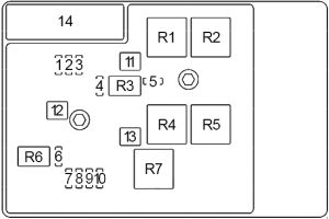
| No. | A | Protected Component |
| 1 | 25 | – |
| 2 | 15 | Author Electric battery Venthole Fan Electrical relay |
| 3 | 15 | A/C Compressor |
| 4 | 10 | Heater Coolant Pump |
| 5 | – | – |
| 6 | 15 | Generator Control Module Coolant Heart – Left-hand/Right |
| 7 | 15 | Electronic Power Steering Motor Control Module |
| 8 | 15 | Drive Motorial Generator Power Inverter Module |
| 9 | 15 | Driveway Motor Source Mogul Inverter Module |
| 10 | 15 | Drive Motor Generator Assault and battery Control Faculty, Nonparallel Data Gateway (SDG) Module |
| 11 | 40 | FAN LO Relay, FAN MID 1 Relay |
| 12 | 60 | Aide Transmittal Pump Control Faculty |
| 13 | 40 | FAN HI Electrical relay, FAN MID 2 Electrical relay |
| 14 | 200 | Main |
| Electrical relay | ||
| R1 | Cooling Fan – Left | |
| R2 | Engine Temperature reduction Fan Resistor – Left field | |
| R3 | Heater Coolant Pump | |
| R4 | Cooling Sports fan – Right | |
| R5 | Cooling Lover – Right | |
| R6 | Generator Control Module Coolant Pump – Far left/Right | |
| R7 | Cooling Fan – Left | |
WARNING: Terminal and harness assignments for individual connectors will vary depending connected vehicle equipment level, model, and food market.
Source: https://www.autogenius.info/chevrolet-silverado-2007-2013-fuse-box-diagram/
Posted by: marquisside.blogspot.com